Description
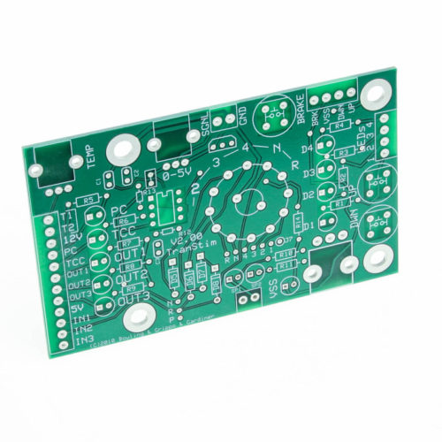
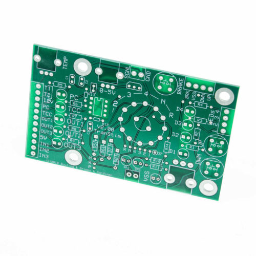
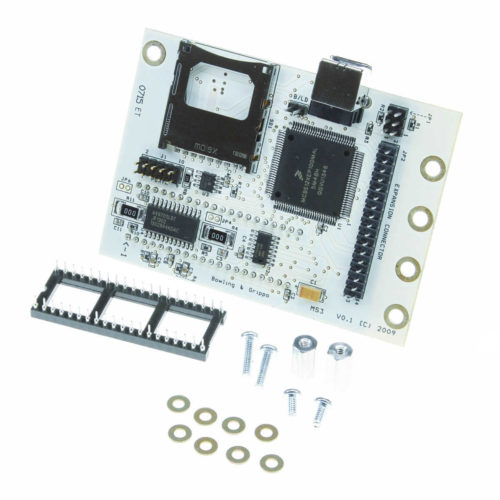
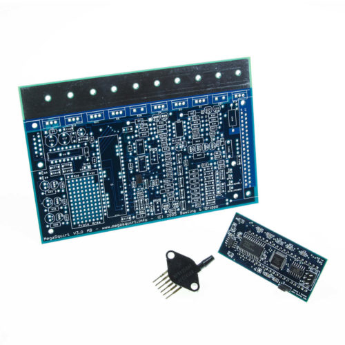
The TransStim simulates a 4L60E transmission, and several others. This is the bare PCB to make one TransStim. Use it to test your MegaShift or other transmission controller.
The TranStim™ will help you to:
- Validate and troubleshoot a newly built GPIO/MShift™ board and harness
- Become familiar with the MShift™ software settings, and
- Distinguish between controller and transmission issues if they arise.
The TranStim™ has:
- All of the essential input and output (I/O) connections for the MShift™ controller,
- VSS signal generator built in with a range from ~9 Hertz (9 times per second) to as much as 30 kilohertz (30 thousand times per second) – up to well over 200 mph with the default parameters. The VSS circuit is equipped with an LED status indicator,
- Seven LEDs to indicate the status of the PC, TCC, Output 1 (SolA on the 4L60E), Output 2 (SolB), and Output 3 (3/2sol on the 4L60E) transmission control solenoids, as well as spare outputs 1 & 2,
- Four LEDs (D1-D4) to indicate the current gear from the controller,
- A rotary switch to set the manual shift lever position gear (the other pole is brought out on a 0.100″ header for those wanting to design their own shift sequence or a custom variable voltage shift lever set-up)
- Four #10 screw holes (3/16″) for mounting or stands, as well as grounding a scope probes or other test devices,
- A pot that can be configured for variable resistance (a Ford shifter, for example) or a 0 to 5 Volt signal (non-CAN load or other uses).
- A pot for transmission fluid temperature feedback.
The board is 2.5″ x 4″. Users can either:
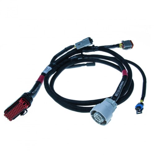
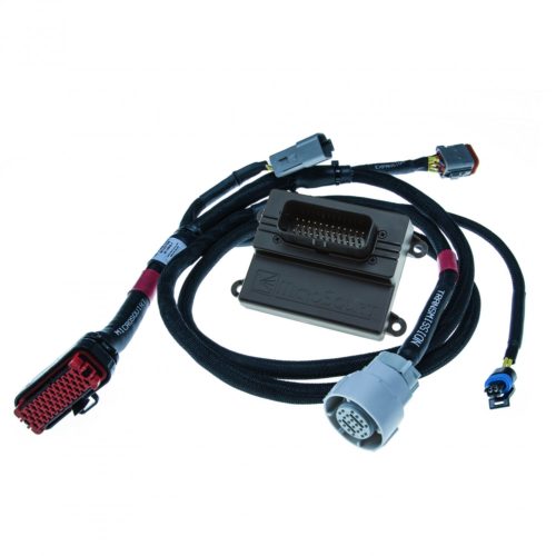
- Plug their ampseal pigtail into this for testing while assembling the GPIO, or
- Use a 4L60E internal connector to test their entire harness (the pigtails are common – transmission shops frequently replace them since they have the TCC solenoid as an integral piece – new they are about $40).
Click HERE for complete TranStim™ documentation.


1 review for TransStim PCB