Last Updated: 2/4/2015
Table of Contents
-
Fuel-Only Implementations
-
Fuel and Spark Control: Standard Distributor Based Ignition Systems
-
Fuel and Spark Control: Other Distributor Based Ignition Systems
-
Going Distributorless: Stock Vehicles with the Ford EDIS or GM DIS Ignition systems
-
Going Distributor-less: Wasted Spark and Coil On Plug (COP) Systems
-
Going Distributorless: Wasted Spark Conversion the easy way, Ford EDIS to the rescue!
Fuel-Only Implementations
Complexity 3/10
Compatible EMS: All MegaSquirt versions
People pursuing Fuel-Only Implementations of MegaSquirt Engine Management Systems won’t really need this article as we’ll be focusing on how to trigger the MegaSquirt from the stock Crank Angle Sensor, a.k.a. Crank Trigger or Trigger Wheel, and sometimes from the Cam Angle Sensor as well in dual trigger applications. For fuel-only implementations you really only need to trigger the MegaSquirt with tach signal which can usually be picked up at the (-) terminal of the coil unless you are running a Capacitive Discharge Ignition, which can put out 400+ volts here. In this case you can often use the tach output of the CD control box.
Fuel and Spark Control: Standard Distributor Based Ignition Systems
Very Common — Complexity 4 or 5/10
Compatible EMS: MS-I with MS1/Extra, MegaSquirt-II, MegaSquirt-III
Distributor (a.k.a. dizzy) based ignition systems are usually the easiest to take control of, and support for standard distributor based ignition systems was built into the MegaSquirt (with MSnS-E) and MegaSquirt-II so there is a huge amount of support there.
So what exactly am I calling a ‘standard distributor based ignition system’?
Basically this would be a distributor based ignition system, with an internal crank trigger mechanism based on:
- Variable Reluctor (VR) Sensor
- Hall Sensor
- Optical Sensor
- Points
Each of these will have a ‘wheel’ or ‘cam’ with a certain number of ‘positions’ we’ll call them. These ‘positions’ will be read by the sensor. For a VR Sensor trigger, these ‘positions’ will be represented by a toothed wheel. The sensor will generally have two wires, and will magnetically read the teeth as they pass by. For a Hall Sensor trigger, these ‘positions’ will be represented by a shutter wheel with windows in it. There will be a magnet on one side of the wheel and a sensor on the other, and the windows and non-windowed areas of the wheel will interrupt and pass-thru the magnetic field which is read by the sensor. For an Optical Sensor trigger, there is an LED (not visible light usually) and a sensor on opposite sides of a flat disc with small slits it in. The slits are the ‘positions’ and let the light pass thru and the sensor reads it. Lastly, points — this is the system I have the least experience with, but it’s still around. With this type of distributor you have a cam with a number of flat areas and lobes. These act as the ‘positions’ in a points setup. The switching arm follows the cam and opens and closes the points.
Here’s a site with a great explanation and animation for a 4 cylinder that will help you to see a full dizzy (distributor) based ignition system in action:
http://auto.howstuffworks.com/ignition-system.htm
Notice ‘Part F’; the item they call the ‘Distributor Cam’. This would probably be more commonly called the trigger wheel, or Crank Angle Sensor Wheel. (CAS Wheel for short). That animation best represents a VR Sensor setup, with a 4-toothed wheel. Notice that the teeth are evenly spaced 90 degrees apart. The distributor spins at cam speed, which is half of crank speed. Which means that for every complete engine cycle (two complete rotations of the crank, or 720 degrees) the cam (and any wheel spinning at cam speed) spins one complete rotation, 360 degrees. So each time a tooth passes the sensor (every 90 degrees of trigger wheel rotation) the crank has rotated 180 degrees. This works perfect for a 4 cylinder car, with one tooth passing the sensor each time a piston reaches TDC (Top Dead Center), or a set number of degrees before or after TDC which the computer accounts for when firing the coil, which is then directed to the correct plug by the distributor. But hold on, maybe I’m making this sound too difficult here, it’s really very simple to be able to see if your setup will be compatible in many cases…
- On a trigger wheel that’s spinning at cam speed and a 4 cylinder vehicle. You’re looking for the four ‘positions’ to be spaced evenly, which will be 90 degrees apart. If they are, you’re good to go, and you can trigger a MegaSquirt-I with MSnS_E, or a MegaSquirt-II with this trigger wheel with no problem!
- Similarly on a trigger wheel that’s spinning at cam speed and a 6 cylinder vehicle. You’re looking for the six ‘positions’ to be spaced evenly, which will be 60 degrees apart.
- Same thing goes for an 8 cylinder, in that case you’re looking for the eight ‘positions’ to be spaced evenly, which will be 45 degrees apart.
Don’t get caught up too much in trying to measure the number of degrees apart — you should be able to tell if they are evenly spaced by looking in most cases. If so the math will be right as 360/4=90, 360/6=60, and 360/8=45.
If it’s a Hall or Optical sensor, you’ll also check to make sure the windows or slits are all the same size, or at least had the same leading or trailing edge. We’ll get into that more later. For now we’ll assume they’re all the same size, if you can see that yours aren’t then read on down the page.
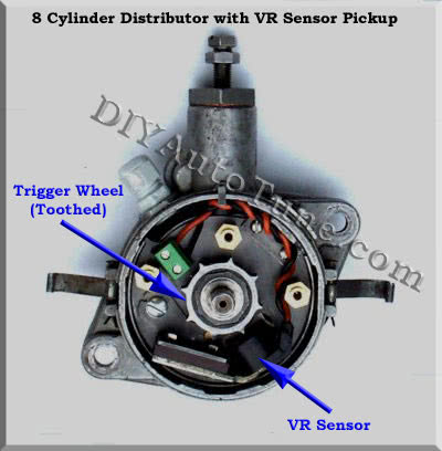
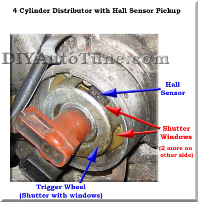
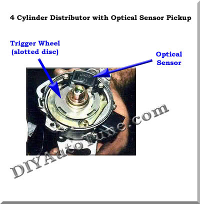
Here are some of the different wheels and sensors:


Notice the 8 cylinder wheel has exactly 8 ‘positions’ (teeth in this case) and they are evenly spaced apart. The two 4 cylinder wheels both have 4 ‘positions’, and though you can’t see all of the wheels due to the angle of the pictures and the sensor placement, they are also all evenly spaced. The other thing too look out for with the hall and optical wheel here is whether or not the ‘positions’ (either windows or slots) are all the same size. These all are so there is no concern.
The quick-n-dirty formula for success — if the number of ‘positions’ equals the number of cylinders, they are evenly spaced, and they are the same size — it will work with the MS-I/MSnS-E, MS-II, and MS-III. All three of the above distributors will trigger the MegaSqyurt just fine!
Note: This is based on the wheel spinning at CAM speed, as the distributor generally does. If the wheel is spinning at CRANK speed, such as when the wheel is mounted to the crank pulley directly, the story is different. But we’re not there yet….
We’ll talk about some of the funkier situations further down. MANY of you will need to go no further as a LARGE percentage of distributor based vehicles will fall into the category above, easily fully supported.
Fuel and Spark Control: Other Distributor Based Ignition Systems
There are four other less common types of wheels you may see when you pop open that hood/distributor.
They are:
- Wheel inside distributor with inconsistently spaced/sized holes
- No wheel inside the distributor, crank or cam mounted trigger wheels instead (no decoding required)
- No wheel inside the distributor, crank or cam mounted trigger wheels instead (decoding required)
- Wheel inside distributor requiring decoding by the ECU
Wheel inside distributor with inconsistently spaced/sized holes
Somewhat Common — Complexity 5/10
Compatible EMS: MS-I with MS1/Extra, MegaSquirt-II or MegaSquirt-III
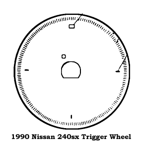
Often these trigger wheels will work just fine as well. Remember you are looking for consistent trigger points (positions) evenly spaced apart. In some cases You’ll have all trigger positions, usually holes on a optical trigger wheel, spaced evenly, but one will be larger than the rest. An example of this are Nissan 240sx and 300zx cars (probably others as well). Here’s a wheel used through most of the 90’s on the Nissan 240sx (KA24E). It has 4 holes, evenly spaced, but one hole is larger than the rest.
What’s important to look for here is if the leading or trailing edge of the holes line up to be evenly spaced apart. So picture this — the MegaSquirt EMS is not so much looking just at the hole itself, but at the beginning and end points of each hole. Where they start and stop. As long as one or the other lines up evenly all the way around then you’re in good shape and triggering the MegaSquirt will be no problem. The above wheel will work just fine with the MegaSquirt-II or MegaSquirt-III set to trigger from the ‘falling edge’. A 12v pullup on the ignition input is needed as well.
The late 80’s Nissan 300zx (VG30E and VG30ET) have a nearly identical trigger wheel inside the distributor, just with 6 positions evenly spaced, and one larger than the rest. This works fine as well. Once again set to trigger on the ‘falling edge’ and with the 12v pullup on the ignition input.
No wheel inside the distributor, crank or cam mounted trigger wheels instead (no decoding required)
Less Common — Complexity 5/10
Compatible EMS: MS-I with MS1/Extra, MegaSquirt-II or MegaSquirt-III
Remembering that what we really need for a distributor based ignition is one trigger event (position) passing the sensor for each cylinder, and they need to be evenly spaced on even-fire engines (which is almost all of them, except Harleys and few other odd-fire motors). This tells the ECU to FIRE the ignition once for each cylinder at the right time so that the distributor can make sure that spark gets to the right place. Let’s say for example you have a distributor without a trigger wheel inside the distributor at all. The ignition system HAS to have a trigger wheel somewhere or the ignition would never fire because it would never know that a cylinder was approaching TDC (top dead center).
1) Trigger Wheel on the cam: Since the cam runs at the same speed as the distributor (1/2 of crank RPM) this would need to be identical to what you’d expect inside the distributor, with the same number of trigger ‘positions’ as the engine has cylinders, and all evenly spaced. Usually this would be a toothed wheel and VR sensor. For a 4 cylinder you’d see 4 teeth, evenly spaced. 6 for a 6cyl, 8 for an 8cyl, etc. This would trigger a distributor based ignition system just like it would if the trigger wheel were inside the distributor itself. No problems here, no special decoding required.
2) Trigger Wheel on the crank: Since the crank runs at full engine speed, which is twice the cam/distributor speed, you only need half as many trigger positions on a crank mounted wheel (evenly spaced of course). This is also usually a toothed wheel with a VR sensor and is mounted on the crank pulley up front, or the flywheel on the back of the engine. Note it can also be a ‘flying magnet’ Hall Sensor setup. The results are the same. 2 trigger points for a 4 cylinder, 3 for a 6cyl, 4 for an 8cyl, you get the picture. This would trigger a distributor based ignition system just fine, as if it had a wheel with twice as many positions inside the distributor itself. There are actually some benefits to this as it takes the cam and distributor shaft out of the loop which can flex just a bit at high RPM. This gets it’s reading DIRECTLY from the crankshaft, so it will tell you EXACTLY where the engine is in rotation without that small margin of error possible with a distributor located trigger wheel. For most of us this is of no concern as it’s a small fluctuation in most cases.
No wheel inside the distributor, crank or cam mounted trigger wheel(s) instead (decoding required)
Somewhat Common — Complexity 7/10
Compatible EMS: MS-I with MS1/Extra, MegaSquirt-II or MegaSquirt-III
There is an ignition system that was often used on European (Porsche and BMW) cars that had no trigger wheel in the distributor but has what’s known as a missing toothed wheel mounted on the crank (pulley or flywheel) with spaces for 60 teeth, but 2 are missing. This is known as a 60-2 wheel, pronounced ’60 minus two’. There are car with other missing toothed wheels as well, maybe a 4-1, 20-1, or 36-1. Some of these you’ll see as a part of a stock ignition system, some may have been custom made to trigger an aftermarket engine management system such as the MegaSquirt.
Both the MS-I with MSnS-E and the MS-II (firmware 2.6 or later, or all MS2/Extra), and all MS-III versions, support a distributor based ignition system being triggered by a missing tooth wheel. You can find a ton more information on this here:
Wheel(s) inside distributor requiring decoding by the ECU
Somewhat Common — Complexity 7 or 8/10
Compatible EMS: MS-I with MS1/Extra, MegaSquirt-II or MegaSquirt-III
Basically the exact same story as above except the wheel or wheels are inside the distributor. It could be a missing tooth wheel, or two wheels that work in conjunction. The most common is an ignition system used by Toyota and Mazda which commonly used this arrangement, where there would be a 24 toothed wheel (evenly spaced, no missing teeth) and a separate 1 or 2 toothed wheel. Sometimes the 1 toothed wheel would have 2 VR sensors, providing two top dead center signals. This is also compatible with the MS-I and MS1/Extra firmware or MS2/Extra firmware. Note you will need a 2nd VR conditioner (mid-level modification) in order to receive the second ignition input signal. See our Zeal Engineering Daughterboard for an easy way to add this. We recommend MS2/Extra with the dual wheels because of its superior noise filtering.
Going Distributorless: Stock Vehicles with the Ford EDIS or GM DIS Ignition systems
Complexity 5/10
Compatible EMS: MS-I with MS1/Extra, MegaSquirt-II or MegaSquirt-III
Several GM Cars came with a compatible distributorless ignition system called GM DIS. This shows up on OBD1 Saturns, Quad Fours, pushrod V6s, and Northstars. Some OBD2 engines are still compatible while others are not. You can find information on compatible systems at the following links:
GM DIS with the MS-I/MSnS-E (mods required) http://www.msextra.com/doc/ms1extra/MS_Extra_Ignition_Hardware_Manual.htm#gmdis
And the wonderful, versatile, and commonly used Ford EDIS system. Here’s more information on this:
Ford EDIS with the MS-I/MSnS-E (mods required) http://www.msextra.com/doc/ms1extra/MS_Extra_Ignition_Hardware_Manual.htm#edis
Going Distributorless: Wasted Spark and Coil On Plug (COP) Systems
Complexity 10/10
Compatible EMS: MS-I with MS1/Extra, MegaSquirt-II or MegaSquirt-III
You can do either wasted spark or COP ignition with the MegaSquirt-I and MSnS-E firmware though it’s probably the most advanced implementation of the systemit requires fitting a missing tooth (12-1, 36-1, 60-2, etc) wheel to the crank pulley and modding the ECU out with extra ignition outputs to drive the COPs. MS2/Extra supports other types of crank wheels as well – click here for a full list. I’d recommend building your ECU from a kit so you’ll be familiar with it when it comes time to mod the unit. The other piece of this is determining the trigger settings for your motor, the guys on the forums (linked below) can help with this.
Here’s the main info on this setup:
Here’s the MS/Extra forums which will be really helpful, both to research what others have done, and for any questions you have that the above link doesn’t answer:
http://www.msextra.com/forums/index.php
It’s a very sweet, though complex, setup. You can do it cheap and super effective — but it’s going to take some work, maybe some frustration, the car being offline for a bit, and then you’ll get it going and have a sense of accomplishment that is simply amazing — if that sounds like fun to you then this is your setup.
The rest of the install is much easier compared to this as it’s pretty much the same across all vehicles (sensors, injectors, etc) and you can use the main MSExtra guide for all injector and sensor wiring.
Going Distributorless: Wasted Spark Conversion the easy way, Ford EDIS to the rescue!
Complexity 6/10
Compatible EMS: MS-I with MS1/Extra, MegaSquirt-II or MegaSquirt-III
If you want or need to go distributorless, and you’d rather stay away from the ‘complexity 10/10’ option above your far simpler option is to adapt the Ford EDIS ignition system — Ford EDIS is a wasted spark distributorless ignition system that’s very easy to adapt to just about any internal combustion piston engine out thereyou just need to mount (weld or bolt) a 36-1 trigger wheel to your crank pulley and build a bracket for the VR sensor to locate it next to the trigger wheel. That’s the hardest part and the only fabrication work. The rest is a bit of wiring. The EDIS system has an EDIS module and a coil pack. The module is wired to the VR sensor and the MegaSquirt, and also the coil pack. The MegaSquirt-II is what I would recommend for EDIS control and will take full control of an EDIS ignition system easily.
Here are some links with more info:
Here’s all the parts that are needed and where they can be found if you wanted to dig them up yourself: http://www.msextra.com/doc/ms1extra/MS_Extra_Ignition_Hardware_Manual.htm#edis

