Directly driving the coil with the MegaSquirt-I PCB 3.0 and MSnS-E 024s9 or later or the MegaSquirt-II
Application: 1982-1983 280ZX Turbo, or conversions using the 82-83 turbo distributor
Updated 10/20/2020 – link to HybridZ.org changed
These same modifications work for the ’84-’89 300ZX, both turbo and non turbo.
Level of control: Full Standalone EMS– Fuel and Ignition Control
There is already a great write-up by ‘mobythevan’ at Hybridz.org on how to MegaSquirt the 280zx turbo using the MegaSquirt-I PCB2.2 ECU, combined with an HEI-4 module, but what about the more recently released PCB3 ECU? Certainly you could use it the exact same way and follow the same document combining the MS with the HEI-4 module and end up with the same result, but what about that snazzy new IGBT High Current Ignition Coil Driver that’s built into the PCBv3.0 ECU? I was recently contacted by a customer that wanted to try and go this route, and I told him I’d make the necessary modifications and document the process for others to follow… so here we go!
Note – want to trigger a distributorless ignition or sequential injection from the stock distributor? We now offer a bolt in trigger disc that gives you that option. It needs slightly different mods and settings; see this article for how to set it up.
ECU Modifications
It’s choice time, MS1 with MS1/Extra firmware, MS2, or MS3. You can use an MS3 with the MS2 mods shown here, although to take full advantage of the MS3’s capabilities, it is better to use our L28ET trigger disc upgrade to allow sequential injection.
These modifications use a BIP373 ignition transistor, sold separately from the kit.
Using the MS-I PCBv3 or V3.57 with MS1/Extra firmware
|
Using the MS-II PCBv3 or V3.57 ECU
|
Wiring
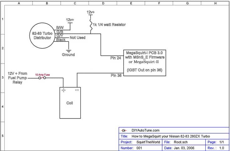
The input side of things will be the same as mobythevan’s setup– it’s the output side of things that will change. Here’s a diagram of how to wire it all up if you’re laying out your own wiring harness. This diagram assumes you are splicing the connector from the OEM Nissan wiring – color designations are for the Nissan wiring harness, not the MegaSquirt wiring.
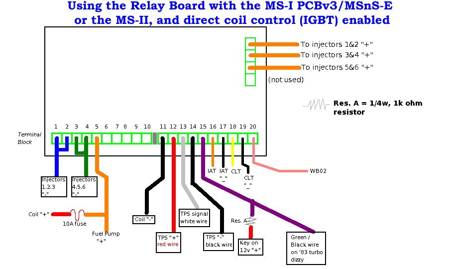
And alternately, here’s a diagram for how to wire up the relay board if you choose to use it:
Thanks to Chris Lupkin for permission to use this drawing
Distributor Wire Colors in the OEM Wiring Harness
Colors of the wires on the distributor side of the 4 pin round connector, versus on the harness side. You can connect in from either side.
| Dizzy Side | Harness Side | Purpose |
| Red | Black / White | 12v+ |
| White | Green / Black | MS Trigger (to Pin 24 on DB37, or Relay Board TACH terminal) |
| Green | Green / Yellow | not used |
| Black | Black | Ground |
On our current harness for standard MegaSquirts, the MS trigger wire is the white wire in the shielded tach input, and the black wire in the shielded tach input is a ground. You can power the distributor from the same source where the MegaSquirt gets power.
TunerStudio Configuration for MS1/Extra
For now, continue to refer to Mobythevan’s documentation for MegaTune configuration of the MSnS-E firmware. You can use the .msq files from PCBv2.2 implementations with this setup– you’ll just need to reconfigure the spark output so that instead of coming from FIDLE it’s now coming from D14 (aka LED17). You can do this from inside MegaTune. Select the ‘Code Config’ Menu, then select the ‘Codebase and outputs function’ option. Set ‘FIDLE function’ to ‘Idle Control’ and set ‘LED17 function’ to ‘Spark Output’.
On the ‘Spark’ menu choose ‘Spark Settings’ and set ‘Spark Output Inverted’ to YES.
If you use someone else’s .msq file, I recommend you check the MSnS-E firmware version the .msq file was built on. You cannot always use a file built on one version of MSnS_E with a different version– it’s best to use the .msq files with the same version of the MSnS-E firmware that it was built on.
TunerStudio Configuration for MS-II B&G code
Start with a trigger angle of 90, and adjust from there with a timing light.
Ignition input capture should be set to Falling Edge.
Coil charging scheme should be set to standard coil charging.
Spark output needs to be set to going high / inverted.
Do not enable dual spark or wheel decoding.
TunerStudio Configuration for MS2/Extra (based on 3.3.3 or later code)
Spark mode: Basic Trigger
Trigger angle / offset: Start at 90 degrees. Adjust with a timing light as needed.
Ignition input capture: Falling edge
Spark output: Going High
Number of coils: Single coil
Spark A output pin: JS10
Dwell type: Standard dwell


