Problem: Power is applied to the VVTuner, but the LED does not illuminate.
Solution 1: Confirm that the polarity is not reversed on the VVTuner connector.
Solution 2: Confirm that the wires are connected in the proper locations on the VVTuner connector.
Solution 3: Confirm the voltage supplied to the VVTuner is no less than 11 VDC.
Problem: A correct RPM Value is shown in VVTuner, but the camshaft never advances
Solution 1: Ensure that the OCV solenoid wiring is connected at both the controller and solenoid. Polarity does not matter.
Solution 2: Ensure that a valid target table is loaded into VVTuner.
Solution 3: With VVTuner running, set the PID values to the following:
- P = 20
- I = 15
- D = 0
Start a data log and observe the change in “PID i”.
Solution 4: With VVTuner running, select from the Menu “Controller -> OCV Duty Cycle Limits and verify the values are within a usable range (I.E. the Low value isn’t too high and the High value isn’t too low).
Solution 5: Confirm proper operation of the OCV solenoid.
Problem: Power is applied to the CCM and the LED is illuminated, but VVTuner will not establish a connection.
Solution 1: Ensure that the serial cable is firmly inserted into the CCM’s serial port.
Solution 2: Confirm that the appropriate communication port is selected within VVTuner. From the Menu, select “Communication -> Settings…”.
Solution 3: Ensure that the selected COM port is not in use by another application.
Problem: The displayed RPM displayed is low and/or wildly erratic.
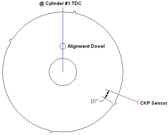
Solution: Verify that the crankshaft trigger wheel is installed in the proper orientation.

.
-
Introduction
-
Software Downloads
-
Installation
-
Communication Settings
-
Tuning
-
Troubleshooting
-
Glossary