In this guide, we’ll walk you through the fundamentals of setting up and tuning Closed Loop Idle Control – PWM Valve. Our aim is to present the information in a straightforward way, making it accessible even if you’re not deep into engine management theory. We’ll provide real-world examples and recommended settings based on the vehicles in our shop.
These settings are used on all our MS3Pro Wire-in & Plug-N-Play ECU’s
In this article for Closed Loop Idle we will cover these settings (TunerStudio MS/Ultra: Startup/Idle):
- Idle Control > PWM Idle
- Closed-Loop Idle Settings (Dependency Settings located: Basic/Load Settings > Engine State Settings)
Achieving a stable idle requires careful consideration of several parameters. It’s important not to focus solely on the idle valve—fuel mixture and spark advance are critical factors that greatly influence idle quality.
Air-Fuel Ratio (AFR)
Idle speed and quality are significantly impacted by the fuel mixture. A target AFR between (.92-1.02 lambda) 13.5 to 15 AFR is typical, depending on your cam profile. The closer you can idle to stoichiometric (14.7 AFR), the better.
AFR plays a key role in how smoothly your engine transitions into and maintains idle. For engines with cam profiles that have excessive overlap, tuning can become more nuanced, often requiring “by ear” adjustments rather than relying solely on wideband readings. This can be challenging for beginners. Here are some general guidelines when wideband readings can’t be trusted:
- Wideband sensors often read leaner than the engine’s actual condition—don’t chase a “normal” AFR
- Exhaust Sounds
- Lean Condition will produce a “hollow” exhaust sound
- Rich Condition will produce a “labored” exhaust sound
- Pay attention to your MAP signal and tune for maximum vacuum
- If the exhaust has a gassy smell, reduce fuel incrementally 3-5% at a time.
Spark Advance
Idle spark advance is one of the most important settings when deviating from stock cam profiles. It’s a powerful tool that can be adjusted to enhance idle stability:
- Don’t use the spark advance setting that yields the best MAP signal at idle
- Maintaining a torque reserve by adding timing can help prevent stalling
- Be cautious—too much spark advance can cause idle hunting
- Experiment with a wide range of spark advance values at idle
- Some engine combinations will require values below 0° for optimal results
- Idle RPM Timing Correction fine-tunes your idle by adding or subtracting timing as RPM deviates from the Closed Loop Idle target
- While effective, this feature can induce idle oscillation in engines with mild cam profiles if set too aggressively.
Idle Valve Position
The idle valve primarily determines the overall idle speed but is less effective for immediate adjustments. Here’s how to approach it:
- Spark Advance adjusts more rapidly than the idle valve
- When transitioning into Idle state the idle valve should be set to open more than necessary to prevent idle speed from dropping too low.
- The valve will then transition from this initial setting to a stable, closed-loop value over a brief period.
Synchronizing Parameters
Getting these elements to work together is key to maintaining a stable idle. Without proper synchronization, achieving a smooth idle speed can be difficult.
Idle Control
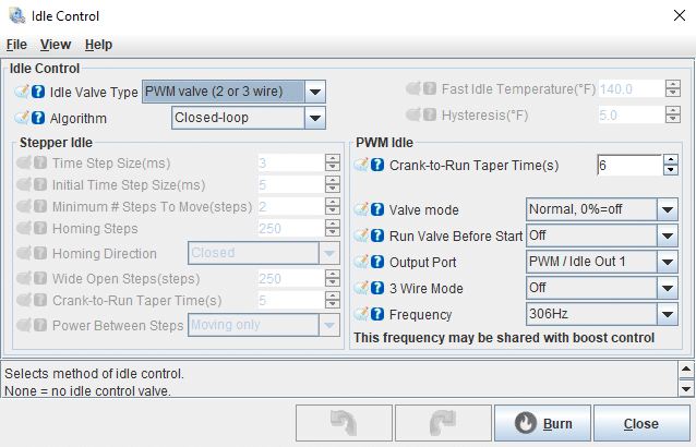
Suggested PWM Valve Settings
TunerStudio MS/Ultra: Startup/Idle > Idle Control
Idle Control
- Idle Valve Type: PWM valve (2 or 3 wire)
- Algorithm: Closed-Loop
PWM Idle
- Crank-to-Run Taper Time(s): 6
- This is how long the Idle valve will take to transition from the Cranking PWM value to the Closed-Loop PWM value.
- Run Valve Before Start: Off
- Some cars have an issue on startup where the idle valve seems to not supply enough air for a clean start, our shop Miata is one of them. To get around this issue we turn Run Valve Before Start ON. This does cause the idle valve to hum and can be audible even with the hood closed.
- Output Port: PWM / Idle Out 1
- 3 Wire Mode: Off
- Default set to “Off” as this is only set if running a 3-wire PWM Valves
- Frequency: 306Hz
- This is the most common Hz for a large variety of PWM Valves
Idle Cranking Duty/Steps
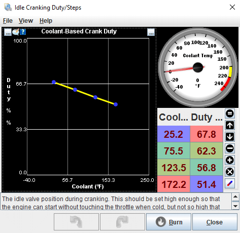
TunerStudio MS/Ultra: Startup/Idle > Idle Cranking Duty/Steps
- Table Usage: this table sets the idle valve position during cranking
- Recommended Duty Position: this is typically set 10-15 points higher than our stable Closed Loop Idle PWM Valve
- Goal: the engine to start and sit roughly 250 RPM above the idle target and then settle into closed–loop
- Rule of Thumb: Fuel does play a large role in getting a clean start. If you have any of the below you will need to focus on Priming Pulse and Cranking Pulse.
- Rich Condition: if the car chugs or labors after startup
- Lean Condition: if you get a start and stall or long crank and stall
- Long crank: can also be a rich condition during startup, if your uncertain which issue you are having you can follow these steps.
- Crank for 3 seconds, then apply throttle until you are over the Flood-Clear threshold, if the vehicle starts then reduce cranking fuel.
- If the above fails prime the fuel system 3 times and crank, if you get a start then increase cranking fuel.
Closed-Loop Idle Settings
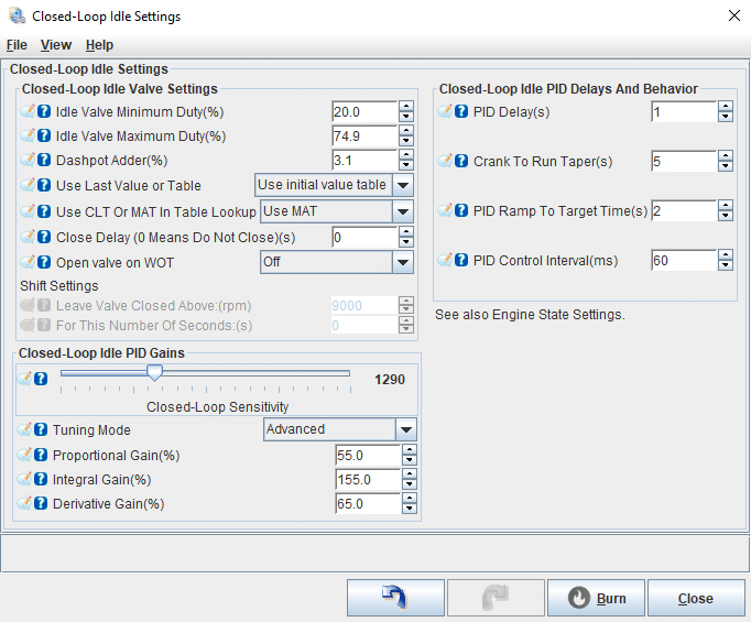
Suggested PWM Idle Valve Settings
Closed-Loop Idle Valve Settings
- Idle Valve Minimum Duty (%): set this value so that the minimum duty allows for an idle speed 50-100 RPM below your hot idle speed
- Typical Range: 20-35% for most idle valves at 306Hz
- If above 35%: Adjust the throttle stop on your throttle body to correct hot idle speed. Use the Test Modes with the idle valve set to 30%, then adjust the throttle plate until you reach your desired hot idle speed.
- Idle Valve Maximum Duty (%): set this to the maximum PWM value that impacts idle speed, usually between 75-85% for most idle valves at 306Hz. The best way to test this is by using Output Test Mode – Idle Valve, which will be explained later in the article.
- Dashpot Adder (%): this value is added to the PWM Duty when the throttle is lifted. Use a small value here since the Closed-Loop Idle Initial Value Table accounts for the needed values to bring the idle speed slightly above the target idle speed.
- Dashpot Adder can be helpful in some applications, but if you rely on more than 5% dashpot, you may need to revisit your Closed-Loop Idle Initial Value Table.
- Use Last Value or Table: We suggest using the Initial Value Table, it is more reliable and once the method to finding the correct value for each RPM column is understood it makes for quick and easy idle setup. We will cover this method later in the article.
- Use CLT or MAT in Table Lookup: use MAT in the lookup table, as air gets hotter it is less dense and may need more duty% to maintain the same reliable return to idle.
- In practice, we have found that most can simply set the initial values needed to obtain a reliable return to idle by rpm column.
- Close Delay (0 Means Do Not Close) (s): a value of 0 prevents the valve from closing and is the recommended starting value, as it can help prevent stalling.
- Allowing the valve to close can help reduce idle speed quickly if it’s dropping too slowly. If you want to experiment with this, a starting value of 3 seconds is recommended.
- Not closing the idle valve can sometimes create a “cruise control” effect where the engine will not decelerate. This is common on automatics.
- Open Valve on WOT: if you experience stalling when returning to idle from high RPM, turning this on may help. These settings are greyed out when Close Delay is set to 0.
- These settings are greyed out if Close Delay is 0
- Leave Valve Closed Above (RPM): this is the RPM threshold above which the idle valve stays closed when you clutch in. Set this high enough to avoid stalling issues.
- For This Number of Seconds (s): this is the maximum time a shift might take. After this timer expires, the idle valve resumes normal behavior. A long shift time could contribute to stalling issues.
Closed-Loop Idle PID Gains
- Closed-Loop Sensitivity Slider: Think of this as an aggressiveness setting, typically adjusted between 750-1350:
- Closer to 750: takes longer to reach the target but helps calm the idle valve with choppy cams
- Closer to 1350: gets the idle valve to the target faster but may cause oscillations with choppy cams
- Goal: the idle valve responds quickly without causing oscillation
- Suggested Starting Value: 1000
- Tuning Mode: Advanced
- Proportional Gain (%): 55-65
- P term: [gain] how large the change made to idle valve position will be in relation to the idle target error.
- Integral Gain (%): 155
- I term: [reset] how often the loop will reset and take another step ( P term ) to reduce the error.
- Derivative Gain (%): 45-65
- D term: [rate] how the loop responds when the error is changing rapidly. This helps stop overshoot of the target.
- Proportional Gain (%): 55-65
Closed-Loop Idle PID Delays and Behavior
- PID Delay(s): this is how long it takes to enter closed-loop control once all conditions are met
- Suggested Value: 1 second
- Crank to Run Taper (s): this is how long it takes to transition from Cranking Duty to the Closed-Loop Target Idle Speed
- Suggested Values: range of 5-9 seconds
- PID Ramp to Target Time (s): this is how quickly RPM matches the Closed-Loop Idle Target RPM
- Set too high: the idle may “hang” before settling
- Set too low: the idle valve may close too quickly, causing the idle to dip
- Suggested Values: range of 1-4 seconds
- PID Control Interval (ms): Suggested values are 60-100 ms
Closed Loop Idle Dependencies
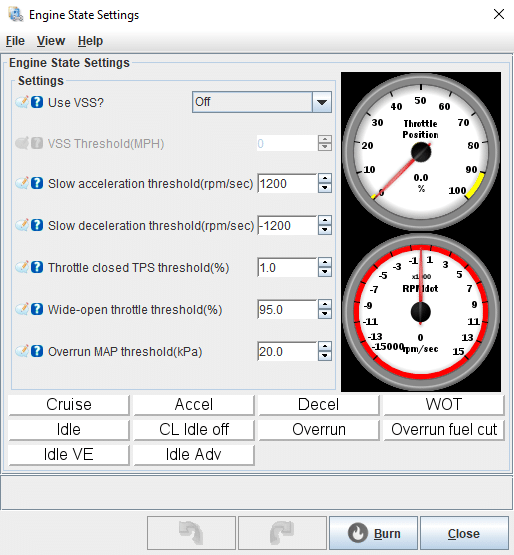
Suggested PWM Idle Valve Settings
TunerStudio MS/Ultra: Basic/Load Settings > Engine State Settings
Engine State Settings
- Use VSS?: this setting will determine if the VSS is used for idle state.
- Recommended Setting: Off
- Off: VSS is ignored
- On: VSS is used and Closed Loop Idle remains at the Initial Value until the vehicle speed (MPH) drops below the specified VSS Threshold. This setting allows for a “rolling idle” and “stationary idle”.
- Rolling Idle: the idle valve will open to the initial value and the idle will remain higher than target. Useful if stalling is a concern.
- Stationary Idle: the idle will enter closed loop and idle down to the closed-loop target idle speed.
- VSS Threshold (MPH): below this MPH value, the ECU switches to Closed Loop and begins idling down
- Slow Acceleration Threshold (RPM/sec): below this RPMdot value, the ECU will enter Closed Loop Idle
- Recommend Starting Value: of 1200 RPM/sec
- Choppy cams: you may need a higher value, but we do not recommend exceeding 1800 RPM/sec
- Slow Deceleration Threshold (RPM/sec): above this RPMdot value, the ECU will enter Closed Loop Idle.
- Recommended Value: of -1200 RPM/sec
- Choppy cams: you may need a higher value, but we do not recommend exceeding -1800 RPM/sec
- Throttle Closed TPS Threshold (%): Setting this value too high can cause incorrect engine state detection at low throttle angles, especially with large throttle bodies.
- Recommended Value: 1%
- Maximum Value: 2% is suggested
- Wide-Open Throttle Threshold (%): above this value, the engine state is considered to be at WOT (Wide-Open Throttle). It is also used for the Closed Loop Idle “Open Valve on WOT” feature.
- Recommended Values: between 90-95%
- Overrun MAP Threshold (kPa): below this threshold, if the engine is decelerating even slightly, it is considered to be in overrun
- Value Setting Recommendation: this setting should be 3-5 kPa above your hard deceleration MAP value, but this is highly application-dependent
- Suggested Starting Value: 20 kPa
- Usage: This setting is used for overrun fuel-cut functionality
Closed Loop Idle Target Curve
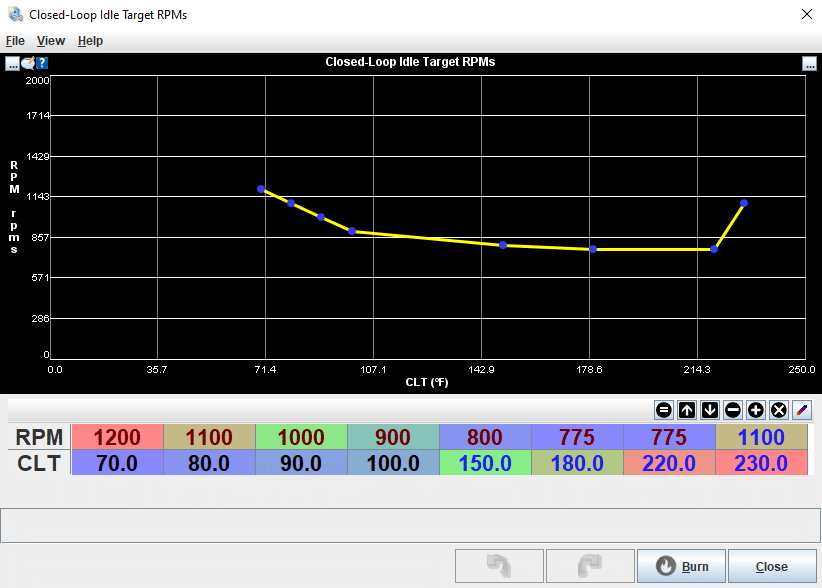
Suggested PWM Idle Valve Settings
TunerStudio MS/Ultra: Startup/Idle > Closed-Loop Idle Target Curve
- Usage: this is where we will set the Closed Loop Idle Target RPM based on coolant temperature. RPM target values will vary based on engine family, modifications, and personal preferences.
- Generally, cams that pull good vacuum will idle smoothly at a lower idle speed than cams that are choppy and have poor vacuum at idle.
-
- If you are having trouble getting a steady idle, increase your target idle speed. You can always come back and lower the target rpm later.
- Overheat Condition: we like to increase idle speed in an overheat condition to get water moving
Closed-Loop Idle Initial Values
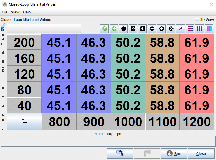
Suggested PWM Idle Valve Settings
TunerStudio MS/Ultra: Startup/Idle > Closed-Loop Idle Initial Values
The Closed-Loop Initial Values table is where you set values based on either MAT or CLT versus the Closed Loop Idle Target RPM. The idle valve moves to this value plus any dashpot adder when in Idle State.
Getting these Initial Values right is crucial for a consistent return to idle. Take your time building this table and avoid rushing through the process. Here’s the recommended method for setting these values, assuming the engine is idling at or near the AFR target and is at full operating temperature:
- Set the Closed Loop Idle Target RPM to 1200 RPM: Adjust the target idle speed using the Closed Loop Idle Target RPM curve.
- Allow the Engine to Stabilize: Let the engine settle at the new idle speed. Monitor Idle Advance to ensure it isn’t adding or subtracting significant timing.
- Confirm Idle Stability: The idle is considered stable when Idle Advance is near 0° (neither adding nor subtracting timing).
- Record the Idle Valve Position: Note the Idle Valve position required for this stable idle and enter it in the 1200 RPM column of the table.
- Adjust for a Smooth Idle Drop: Add 5-10% to the value in the RPM column. This adjustment ensures that the idle drops in above the target idle speed and settles smoothly into closed loop.
- Test and Fine-Tune: Blip the throttle and observe how the idle returns:
- If RPM drops below target and recovers: Add more to the value in the RPM column.
- If RPM overshoots and hangs above target: Decrease the value in the RPM column.
- Repeat for All RPM Points: Continue these steps until the Initial Values table is fully populated.
Important Note: AFR and Spark Advance have a significant impact on idle behavior, and all three parameters (Idle Valve Position, AFR, and Spark Advance) must work together to achieve a stable idle.
PWM Idle Voltage Compensation
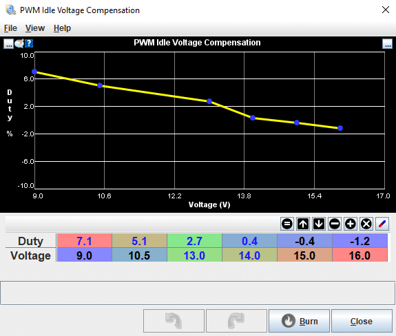
Suggested PWM Idle Voltage Compensation Settings
As battery voltage drops, a PWM idle valve may require more duty cycle to maintain a stable idle speed. This setting helps account for those variations.
When to Consider Voltage Compensation:
-
- Typically, this isn’t a concern unless the vehicle has a weak charging system.
- It can be particularly helpful in preventing stalls when multiple electrical loads (e.g., headlights, fans, AC) are active simultaneously.
Air Conditioning Idle-Up
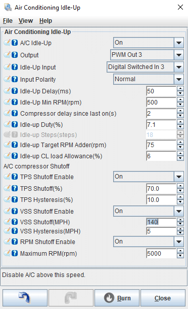
Suggested Air Conditioning Idle-Up Settings
Air Conditioning Idle-Up
- A/C Idle Up: turn the feature On or Off
- Output: What output pin control the compressor?
-
- Not all vehicles have the compressor controlled by the ECU.
- Example: 87-93 mustang compressor is not controlled by the ECU, instead they are equipped with a wot relay. If you want to control the compressor simply re-pin the relay. [pin 87a moves to pin 87] and then setup the output.
- Not all vehicles have the compressor controlled by the ECU.
- Idle-Up Input: What Input pin will trigger the AC feature?
- Input Polarity
-
- Normal: means the input is pulled to ground to activate
-
- Inverted: means the input is NOT pulled to ground to activate
- Idle-up Delay(ms): How long do we want to wait after the input is triggered to activate the output?
-
- Typical values 50-250ms
- Compressor not controlled by ECU set to 0
- Idle-up Min RPM(rpm): If the idle speed drops below this value the AC will de-activate.
- Compressor not controlled by ECU set to 0
- Compressor delay since last on(s): This is to prevent short cycling the compressor
- Compressor not controlled by ECU set to 0
-
- Idle-up Duty(%): How much PWM duty to add to the idle valve when AC is turned on.
-
- Set this by running the AC while watching the stable idle PWM
-
-
- AC OFF: value of 35% and AC ON value of 43%
-
-
-
-
- Idle-up duty (43-35) = 8%
-
-
-
-
- Sometimes this is not enough, and a few extra percent may be needed.
-
- Idle-up Target RPM Adder(rpm): when the AC is running do we want to increase the target idle speed?
-
- This is not always necessary, larger displacement engines can often add 0
A/C Compressor Shutoff
- TPS Shutoff Enable: turn the feature On or Off
-
- The compressor should be off when the engine is under heavy load
- TPS Shutoff(%): suggested 70%
- TPS Hysteresis(%): suggested 10%
-
- Hysteresis is a deadband to keep the output off until the value drops (10%) below the shutoff value.
- VSS Shutoff Enable: turn the feature On or Off
- VSS Shutoff(MPH): above this mph shutoff the AC
- VSS Hysteresis(MPH): suggested 5mph
-
- Hysteresis is a deadband to keep the output off until the value drops (5mph) below the shutoff value.
- RPM Shutoff Enable: turn the feature On or Off
- Maximum RPM(rpm): above this rpm shutoff the AC
Idle Advance Settings
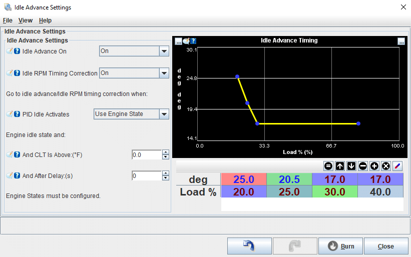
Suggested Idle Advance Settings
Idle Advance Settings
Idle Advance On: Enable or disable the Idle Advance feature
Idle Advance Timing: This feature uses a dedicated timing curve that activates only when the engine is in the “Idle” state (as determined by Engine State Settings) and the Idle Advance feature is ON. It allows Ignition Table 1 to be optimized without affecting idle control.
- Tuning Tips:
- Avoid the Spark Advance that gives the Best MAP Signal: While it may seem counterintuitive, the spark advance that gives the best MAP signal at idle is not ideal. We aim to maintain a torque reserve, allowing additional timing to prevent stalling conditions.
- Prevent Idle Hunting: Too much spark advance can cause the idle to oscillate (“hunt”). Test a wide range of spark advance values at idle to find the sweet spot.
- Common Idle Spark Values: Typically, spark advance values between 5° and 20° are used at idle. Some applications may even require spark advance below 0° to achieve the desired idle speed and stability.
- Optimize the Curve for Stability: Set the curve so that lower load values have higher ignition advance values. This helps smooth out the transition to idle.
- Deceleration Behavior: Setting low ignition advance values at low load can create a “burble” during deceleration events, which may speed up the drop to idle. However, this could also lead to stalling issues.
Idle RPM Timing Correction: Enable or disable the Idle RPM Timing Correction feature
- Suggested Setting: We recommend keeping this feature ON.
See Idle RPM Correction Curve for Additional Details.
PID Idle Activation Conditions
Use Engine State: The feature activates based on the engine’s idle state, combined with the following conditions:
- And CLT is Above (°F):
The feature only activates when the coolant temperature (CLT) is above this value.- Suggested Value: 0°F
- And After Delay (s):
Once all conditions are met, the feature waits for this delay before activating Idle Advance.- Suggested Value: 0 seconds
Idle RPM Timing Correction Curve
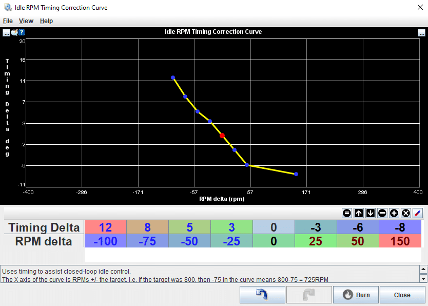
Suggested Idle RPM Timing Correction Curve Settings
Idle RPM Timing Correction Curve
The Idle RPM Timing Correction Curve is a powerful tool for achieving a stable idle speed, similar to how OEM systems work. Spark Advance has an immediate effect on idle speed, making this feature essential for fine-tuning idle performance.
Key Concepts:
- Torque Reserve: To properly use this feature, you need a torque reserve. If the idle advance is already too high, adding more timing won’t increase torque.
- Adjusting Idle Speed with Timing: Increasing torque raises idle speed, while decreasing torque lowers it. This is controlled by adjusting the spark timing.
How It Works:
- Timing Delta: This is the amount of timing to add or subtract to help maintain the Target Idle Speed. The Timing Delta is applied to the Idle Advance (or Ignition Table) value.
- RPM Delta: This measures how far the RPM is from the Closed Loop Idle Target. For example, if your idle speed is 800 RPM and your target is 750 RPM:
- RPM Delta = 800 – 750 = 50 RPM
- With a Timing Delta of -6°, the Idle Advance would adjust as follows:
- Idle Advance = 17° + (-6°) = 11°
Tuning for Your Desired Idle: This feature allows you to shape the idle to your preference. Here are some examples:
- Choppy Idle with Aggressive Correction: For a pronounced “chop,” use a tight RPM Delta with aggressive Timing Delta values, paired with a lower Idle Spark Advance.
- Example Setup:
- Idle Spark Advance: 10°
- Timing Delta: (20, 14, 7, 5, -5, -7, -7, -7)
- RPM Delta: (-100, -75, -50, -20, 20, 50, 75, 150)
- Example Setup:
- Smoother Idle for Stock or Mild Cams: Smaller displacement engines, stock cams, and inline engines generally require less aggressive Timing Correction, especially at low RPM Deltas.
- Example Setup:
- Idle Spark Advance: 15°
- Timing Delta: (9, 5, 2, 0, 0, -2, -4, -5)
- RPM Delta: (-150, -100, -50, -25, 25, 50, 100, 150)
- Example Setup:
Idle VE Settings
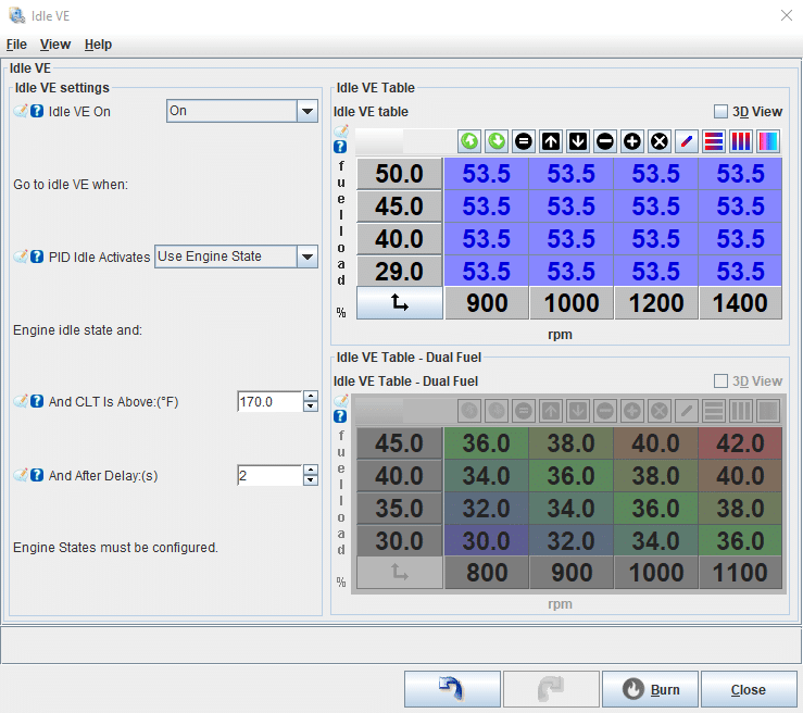
Suggested Idle VE Settings
Idle VE Settings
Idle VE On/Off: This feature can be turned on or off. It’s best practice to initially tune your main VE table with this feature OFF. Once the main VE table is dialed in, you can enable Idle VE if needed.
Go to idle VE when:
- PID Idle Activates: We recommend setting this to “Use Engine State” for more precise control.
Engine Idle State and:
- And CLT Is Above:(°F): Set this temperature slightly below your hot idle temperature to ensure smooth activation. For example, if your engine runs with a 190°F thermostat, it typically maintains a temperature above 190°F after heat cycling. In this case, a CLT setting around 185°F would be appropriate for switching to Idle VE.
- And After Delay:(s): After the engine reaches the idle state and all conditions are met, a delay helps avoid false activations. We suggest starting with a delay of 2 seconds.
Output Test Mode – Idle Valve
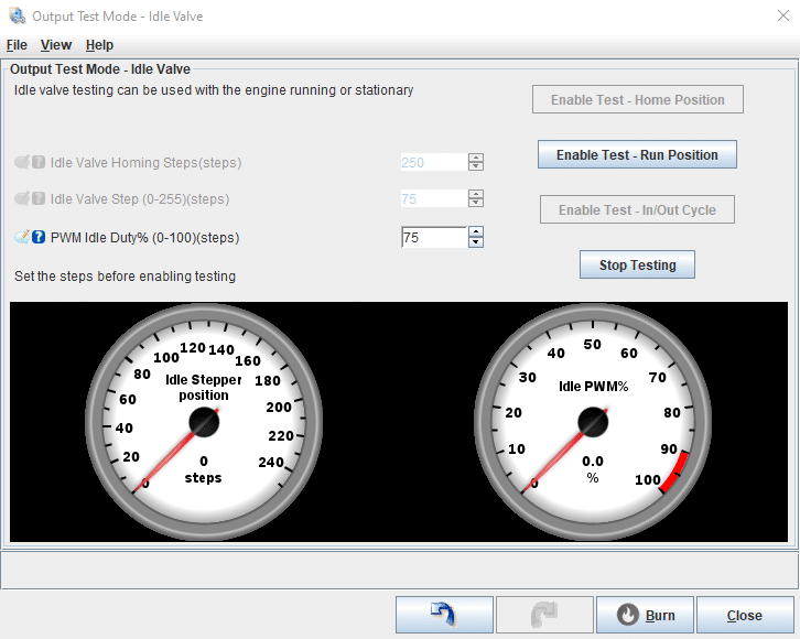
Test Mode Features
Important Note: Test Mode features should never be used while the vehicle is in motion. These features are designed solely for setup and diagnostic purposes.
Output Test Mode – Idle Valve: This feature operates only while the Test Mode dialog box is open and visible. Closing the dialog box will deactivate the test mode.
- PWM Idle Duty (%): Set the PWM value to control the idle valve position.
- Enable Test – Run Position: This function forces the idle valve to move to the Run Position using the PWM value specified in the Idle Valve Step.
- Stop Testing: Ends the test and returns the idle valve to its normal operational mode.