Description
DLP-TXRX Internal USB/Serial Adapter
This adapter is perfect for converting your Megasquirt from the standard DB-9 serial connection to the USB connection common on newer laptops. The DLP-TXRX can be used on the following MegaSquirt products:
- MS1 V2.2
- MS1 V3.0
- MS2 V3.0
It is not recommended for the following MegaSquirt products:
- MicroSquirt
- MS1 V3.57
- MS2 V3.57
- MS3 V3.0
- MS3 V3.57
- MS3 Pro
- Any MSPNP
Also you can get your USB Tuning Cable Here
USB Installation on MS v2.2 and v3.0 PCBs
When installing this USB board, you cannot have the MAX232CPE (U6) connected to the ECU.
- If you have it in a socket, simply removing it will be perfect. If you are able to remove it you will need to disregard any references to cutting the PCB traces mentioned later.
- If you have already soldered U6 to the PCB unsocketed, then you need to remove the connection between U6’s pins 11 and 12 and the CPU’s pins 12 and 13 or USB will not work. This can be done three different ways:
- Cutting the traces on the PCB as shown in the pictures below.
- Desolder pins 11 and 12 of U6 and pull them back through the PCB .
- Be sure to remove all of the solder from these pins before attempting to pull them back through the PCB. If you fail to remove all the solder, you will quite possibly pull the pins out of the U6 chip rather than from the PCB which will leave U6 useless.
- Remove pins 12 and 13 of the MS CPU from it’s socket since it is socketed.
- CAUTION: When later soldering to these leads directly, excessive heat can cause the EPROM to fail!
Each picture is color coded below so you can simply attach wires to each assigned place between the USB and MS PCBs.
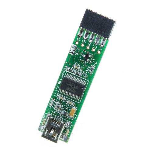
Here is the USB board which converts the processor’s serial communications. The black “box” on the right of the picture (with the text on it) has holes on the end for connections to be plugged in. The easiest way to plug it up is to solder some spare cut off resister leads to a wire and then run the wire back to the appropriate location on the PCB. You can then easily plug and unplug the cut off lead into the usb adapter.
The connections on the black area of the usb connector are pretty close together so it would be a good idea to put some heat shrink over the connections between the cut off resister lead and the wire so you don’t have any shorts.
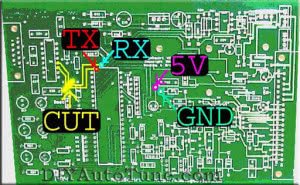
Here are the connection points for the PCB V2.2
- GND – This is a ground point. The picture above uses the left side of D4 (typically does not have a diode installed).
- 5V – You can get this from any 5V reference voltage on the PCB . The picture selected an access point about 1/8” to the left of C11 and the GND.
- TX – Located at the top (and slightly under the border) of the CPU’s socket.
- In order to make sure that you have the correct hole, test for continuity between CPU pin 12 and the hole.
- RX – Located just above and to the right of the TX hole.
- In order to make sure that you have the correct hole, test for continuity between CPU pin 13 and the hole.
- CUT – You do not need to do this if you have U6 socketed or you have chosen to desolder pins 11 and 12 from U6 pulling them back through the PCB .
- Please note the traces are lined in yellow in the picture so you can make sure you are looking at the right ones.
- Slightly score the MS PCB traces which go from the access holes to U6.
- As you score the PCB , you will reveal tiny wires beneath the PCB’s protective coating. You need to CUT these wires so U6 is no longer directly connected to the CPU.
- Test for continuity between the access holes (labeled TX and RX) and U6 pins 11 and 12 to make sure the connection has been severed.
- CAUTION: DO NOT cut through the PCB!
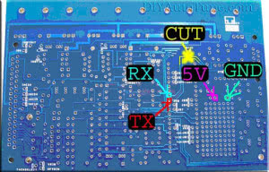
Here are the connection points for the PCBV3.0
- GND – This is a ground point. The picture above uses the GND located in the Prototype area of the PCB
- 5V – You can get this from any 5V reference voltage on the PCB. The picture above uses the 5V located in the Prototype area of the PCB.
- TX – Located at pin 12 of the CPU socket from below.
- RX – Located at pin 13 of the CPU socket from below.
- CUT – You do not need to do this if you have U6 socketed or you have chosen to desolder pins 11 and 12 from U6 pulling them back through the PCB.
- Please note the traces are lined in yellow in the picture so you can make sure you are looking at the right ones.
- Slightly score the MS PCB traces which go from the CPU socket which you just attached the TX and RX wires.
- As you score the PCB, you will reveal tiny wires beneath the PCB’s protective coating. You need to CUT these wires so U6 is no longer directly connected to the CPU.
- Test for continuity between the access holes (labeled TX and RX) and U6 pins 11 and 12 to make sure the connection has been severed.
- CAUTION: DO NOT cut through the PCB! Since the v3.0 MS PCB is a multi-layer PCB, do not cut any further than necessary as you may cut into the 5V or GND internal layers which could lead to other problems down the road.
Document written by Fastest95PGT
Completed v2.2 ECU
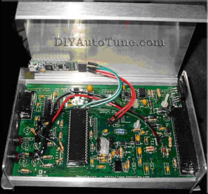
The USB board’s underside was velcroed to the top of the MS case so that it can be allowed to be removed later if needed.
If your computer does not recognize the DLP-TXRX, you can download the appropriate VCP (Virtual COM port) driver from the DLP Design drivers page.
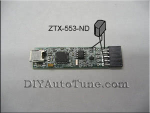
Some older MS2s have a problem with going into bootloader mode if powered up using the DLP-TXRX without a laptop connected. If your MS2 has this problem, we recommend modding it with a ZTX-553 or equivalent transistor soldered to the DLP-TXRX to put its output to 5 volts when there is no computer connected.

5 reviews for DLP-TXRX Internal USB/Serial Adapter