Greg Banish, Calibrated Success

Before we ever begin tuning our delivered air to fuel ratio in the engine, we have to make some decisions about fuel delivery and calibration. I will preface this with the usual requirement that we also have complete injector characterization data (flow rate, offsets vs voltage, short pulse nonlinearity compensation) before programming the controller. But, assuming that we have that, we also need to decide how we will time the fuel delivery to the cylinder events. Sequential vs Batch Injection — what is better?
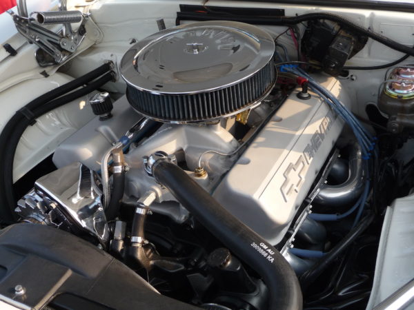
In a carburetor, we have a more or less constant stream of fuel being mixed with a more or less constant stream of airflow through the venturis. Fuel droplets mix with the airflow and either evaporate on their way to the inlet valves or they impact the walls of intake manifold to be evaporated (and mixed with the airflow) later. During steady state or WOT operation this works surprisingly well. The cylinders, pistons, and spark plugs don’t know that the engine is carbureted. They just see a well-mixed charge that is available for combustion.
When we step from carburetion to fuel injection, we gain the ability to more precisely dose the delivery of fuel to each cylinder. Done properly, it allows us to ensure that each cylinder gets the same amount of fuel in the same relative state of evaporation and mixing. However, if we deliver a chunk of fuel to a cylinder that isn’t completely evaporated or mixed with the air charge, we can get poor combustion quality.
Let’s first take a look at a couple different popular EFI layouts to better understand what we’re up against here.
First up is Central Port Injection (CPI). CPI is basically replacing the carburetor with one or more fuel injectors at the same location. The injectors may either be pointed down the throat of the throttle plate(s) or they may be arranged to fire in from the sides just below the throttle blade(s). Either way, fuel is sprayed intermittently at the point where air is just entering the intake manifold. These systems usually carry over the same single or dual plane intake manifold that we would use on the carbureted engine. The Injectors spray into the inlet throat of the intake manifold with lots of their spray hitting the opposing surface, creating significant puddling throughout the manifold much like the carburetor (but often worse). Due to the large distance between the intake valves and the point of injection, the timing of fuel delivery at the throat has almost no consistent correlation with actual delivery timing into the individual cylinders. At WOT, this approximates constant flow like a carburetor, but at idle and cruise the injector pulses are random at best compared to cylinder events, creating a potential concern for distribution. In the Sequential vs Batch Injection discussion, this is an example of Batch Injection.
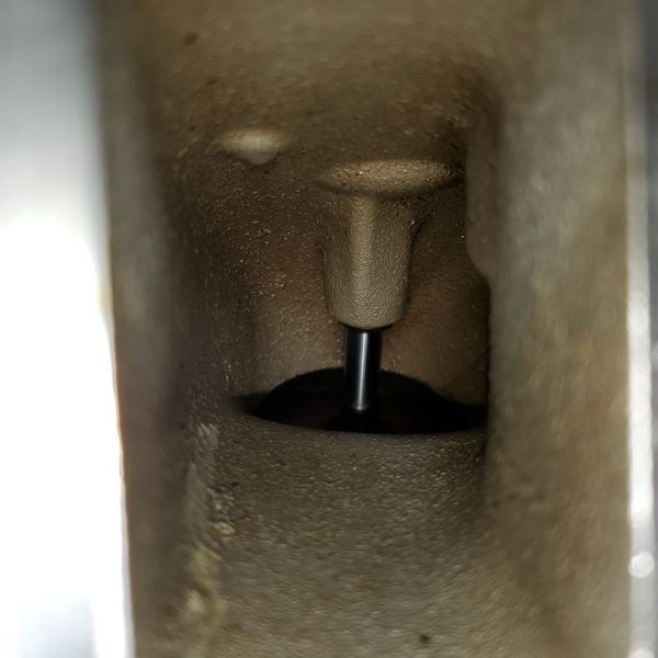
OK, fine, let’s move the injectors closer to the cylinders with Multi-Port Injection (MPI). With the injector installed near the exit of the intake manifold, there is now a direct line of sight to the intake valve for that cylinder. Finally, we have more correlation between the fuel flow though a single injector and the actual fuel delivery to that matching cylinder. Reducing the port and runner volume along with the surface area between the two means that there is less opportunity for fuel puddling and more direct connection between injector spray and fuel delivered on each stroke IF they work together. This enables us to individual control the injection to each individual cylinder IF we’re using the ECU to do so. In the Sequential vs Batch Injection discussion, this is the first requirement for sequential injection, but there’s a bit more too it we’ll get to below.
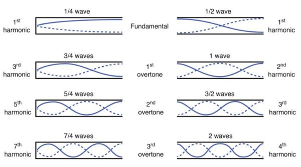
The trick comes when we recognize that the intake runners behave much like a musical instrument with waves of pressure traveling up and down them, influencing the movement of air and fuel. These waves can pull the fuel into the cylinder or carry it back toward the central plenum depending on the phase at the point and time of injection. Essentially, we must decide just how important it is to inject the fuel at one specific point in the cycle, whether that’s on an open or closed intake valve. We can accomplish this with MPI if we arrange the injector firing order to match the engine firing order, which is the same as the intake valve opening order. Doing so determines how long the fuel pauses in the intake port (and potentially moves back toward the plenum as it continues to evaporate) before entering the cylinder on the intake stroke.
This is where we finally get to see the difference between the two popular injector timing strategies.
Sequential vs Batch Fuel Injection: What the waveforms look like
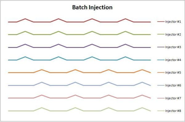
Batch firing means that groups of injectors are opened simultaneously and close simultaneously. There may be more than one batch in engines with more cylinders, but the injectors are operated as groups rather than individuals. One advantage of this is that fewer injector driver circuits are required in the ECU. Systems like the MicroSquirt could have four (or more, in some cases) injectors running in parallel on one injector driver output circuit. This helps keep cost and complexity down on basic installations. The tradeoff here is that, as mentioned previously, we don’t have the ability to consistently line up each injection event with the matching intake valve event.
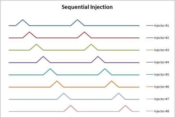
If our ECU is equipped with more individual injector driver outputs and the software supports it, like the MS3Pro, we can switch fuel delivery to a fully sequential delivery scheme. Here, we map the injector outputs to their corresponding cylinders and open them one at a time as each cylinder reaches the desired opening point relative to TDC. Now all cylinders receive their fuel shot at the same point relative to the intake valve opening event. This point can then be adjusted inside the ECU calibration tables to optimize combustion quality. This significantly improves the consistency of the air-fuel mixture between cylinders, meaning that combustion events from all cylinders are more similar to each other and exhaust oxygen sensor readings will also be more stable.
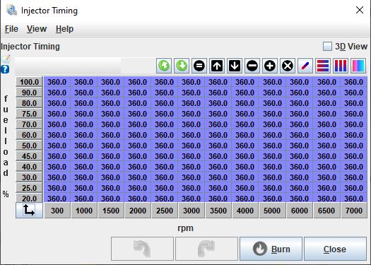
Once we have control over the phasing of injection time for all cylinders, we can tune this timing to find the point that works best for our engine. This injection timing has the biggest impact when the pulse width is very small at idle and light throttle cruising conditions. By moving the end of injection timing, we often see a change in reported air-fuel ratio by the oxygen sensor. If all we did was adjust injection phasing (and not actual pulse width), this means that we somehow affected the burn quality inside the cylinder. Our object here is usually to make sure that as much of the fuel is able to burn during the useful part of the combustion cycle, so we want to adjust this timing for the most complete burn possible.
Generally, I adjust the end of injection until I see the richest reading on my wideband, even if this is richer than my open loop target. This just means that the fuel being injected was now reacting more completely with incoming air. I can go back and fix (reduce) my volumetric efficiency or MAF tables later to bring actual open fuel delivery back on target now that injection timing has been adjusted for the most complete burn. It may sound like a lot of extra work, but it only takes a few minutes and the results can be significant for both stability and fuel economy.
Once you see the effect of adjusting injection timing on a synchronized sequential injection system, you will begin to understand why it was so hard to get a stable idle with a batch fired MPI or CPI system. Imagine the differences between cylinders in effective air-fuel ratio as each one has a different amount of fuel delivered in a different state of vaporization and mixing. Sometimes it works OK, sometimes less so.

But wait, there’s more!
The good news here is that as we approach WOT, injector pulse width become longer in order deliver enough fuel to match the increased air charge. Depending on the injector flow rate, how much total fuel is required and how long the cycle time is at the current engine speed, we often find that the question is no longer “when is the injector open?” Instead, when injector duty cycle exceeds just 50%, it means that the injector is open more often than it is closed. So now the question becomes “when isn’t the injector open?” As we approach high duty cycles of 70% or more, the fuel delivery begins to mimic the constant flow of the carburetor and injection start/stop timing becomes irrelevant. It’s at this point that there is functionally no real difference between sequential vs batch injection.
Auxiliary Fuel Delivery
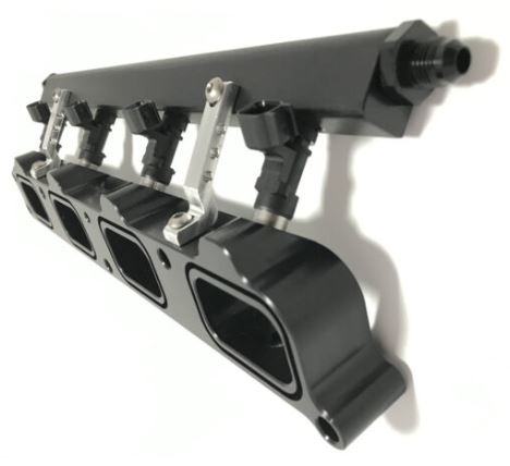
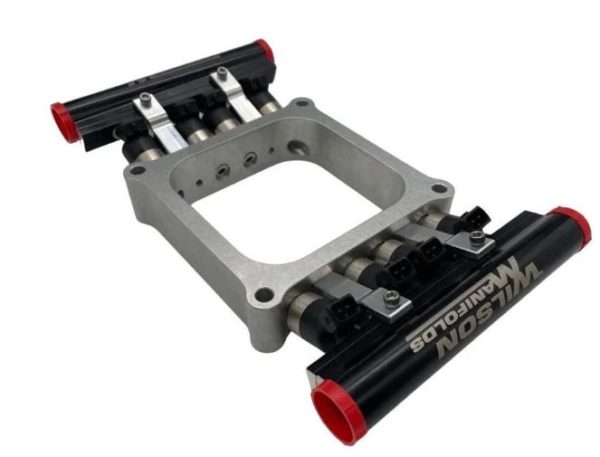
While most readers are considering injection timing strategy on the PRIMARY (and often, only) fuel delivery system for their engine, there are others who a standalone EFI system as an auxiliary or supplemental fuel delivery to their primary OEM ECU and injectors. This is most popular in high output Direct Injection engines like the GM LT1 and LT4, early Ford EcoBoost or BMW N54 and B58 families. For them, increasing fuel delivery through the factory DI system requires injectors and high pressure pump upgrades costing thousands of dollars that may still negatively impact combustion quality at idle and cruise. Adding a supplemental PFI or even MPI system to these engines that only comes on at WOT when the extra fuel is required fixes their issue with lower cost and has the side effect of cleaning their intake valves during operation as well. The biggest challenger here is installing the new injectors, which usually means a new intake manifold or spacer plate kit with injector bungs and fuel rail support.
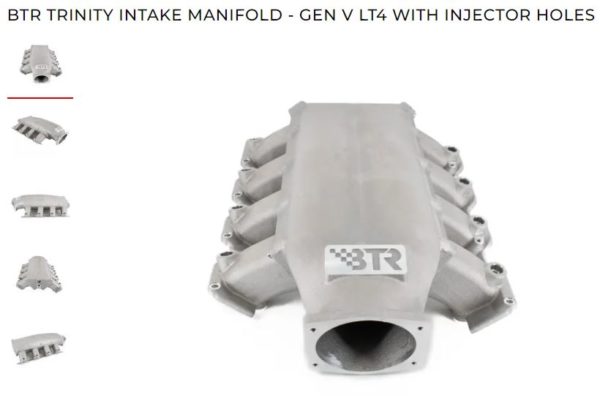
Since these supplemental systems are really only needed at WOT, we remember that injection phasing is almost irrelevant for them. Port velocity is high and, with proper injector sizing in the auxiliary port injection system, duty cycle is relatively high too. This means that we should expect good mixing of the port injected fuel entering the cylinders.
One key here is to avoid choosing too large of a fuel injector for such a system. If you use eight 1000cc/min injectors just to deliver 400hp of fuel, you’ll have smaller pulses with poorer mixing than if you were only using 400cc/min injectors. The smaller injectors will also blend easier with the primary fuel system as they first come on because their minimum fuel mass delivery is so much smaller as well. You don’t get a massive hit of richness just as they are activated. Save money here with smaller injectors and enjoy better overall performance.
www.calibratedsuccess.com
www.diyautotune.com

