(or other Toyota VAST Ignition Vehicle)
Want to make your install as easy as possible? Our MSPNP fully assembled, plug and play, ready to run unit that makes installing MegaSquirt a snap. Click here for MSPNP installation instructions and you can order them here.
For those who’d rather set this up the DIY way, read on.
Also– if you haven’t already, please read the ‘disclaimer’ at the top of the parent page here.

This documentation is for using the MegaSquirt-N-Spark Extra firmware version 024s9 or later. (I’m currently running 029v)
Applications
- 1985-1989 Toyota MR2 Naturally Aspirated
- 80’s 4AG powered Corollas with the VAST ignition system, including AE86 and AE92 models
- The basic info here can be used, with mild adaptation, for basically any Toyota with the VAST ignition system…
Background
The USDM 4ag bluetop motor works great with the MegaSquirt- it uses the Toyota VAST ignition system, and it’s easy to control. I run this on my MR2 with a harness adaptor I built up using the documentation in this message, and many others have built the harness adaptors and successfully ‘squirted their 4ag’s and 22r’s with this doc as well. I don’t offer a ready built harness as they are a bit labor intensive, which is fine for a one-off, horrible for a business ;). There was a guy who does this but I’ve had to help a couple of his customers ‘fix’ their adaptor harnesses due to improper wiring that damaged their MS CPUs— I recommend building the adapter yourself so I’ll give you all the info you could possibly need to do so here.
Which Platform?
First off you’ve got to decide which hardware and firmware you want to go with. What are your priorities?
- Cheap and very functional? The MS-I PCB2.2 running the MSnS-E firmware will do the trick just fine.
- Robust and Upgradeable? The MS-I PCB3.0 running the MSnS-E firmware will do great and is built on the latest PCB with several new features for added robustness. (Basically it’s much harder to blow it up) It also has a longer lifespan from an upgrade perspective due to the newer PCB.
- Robust and ‘Latest Greatest’? The MS-II PCBv3.0 is built on the same new robust/upgradeable circuit board, and uses the new MS-II processor which is much faster and the focus of rapid code development as we move forward.
OPTION A: Cheap and functional. The MS-1 PCB2.2 with MSnS-E firmware.
There’s no need for me to recreate the wheel here, Jamesl, the pioneer of this implementation of the MegaSquirt and the creation of the VAST PnP Wiring Harness Adapter, thoroughly documented this process back in late 2004. One week later I had my 86 MR2 running on a MegaSquirt-I PCBv2.2 by following Jame’s documentation to the letter. He was shocked that it worked as well as it did, and all I could say was thanks. 🙂 Since then he’s brushed it up further and made some improvements for clarity and such. If you’re running a MS-1 PCB2.2 you can go straight to the original source here:
My map for a stock 1986 MR2 bluetop 4AG, built on MSnS-E 024s9
Note that the above linked map is best used with 024s9 as noted, the tables are setup for boost BUT NOT TUNED FOR BOOST. Use this as a base map and expect to do some tuning to get it just right for your car. And as always, USE THIS MAP AT YOUR OWN RISK!
YOU are responsible for tuning your car, this may help you though….
My map for my 4AGTE turbo (8.5psi) 1986 MR2 (bluetop 4AG), built on MSnS-E 029q2
T25 at 7psi
7MGTE 42lb (430cc) injectors
Custom Magnaflow exhaust
Note that the above linked map is best used with 029q2 as noted, the tables are setup for boost and tuned up to 7psi, NOT ABOVE THAT. Use this as a base map and expect to do some tuning to get it just right for your car. And as always, USE THIS MAP AT YOUR OWN RISK!
YOU are responsible for tuning your car, this may help you though….
OPTION B: Increased Robustness and Upgradeability. The MS-1 PCB3.0 with MSnS-E firmware.
This is very similar to Jamesl’s PCB2.2 implementation, I’ve just adapted it for use with the newer MS-I PCB3.0 and moved the spark output over to pin36 which will make your harness adapter MS-II ready should you ever decide to upgrade. It also makes FIDLE available, but you probably don’t care much about that as the TVIS intake manifold have a nifty coolant activated idle valve that’s completely mechanical and not ECU controlled.
Start by reading Jamesl’s document linked here: Jamesl’s Article
Changes from Jamesl’s article for the PCB3 MS-I Implementation:
Then, since you’re using a PCB3 MegaSquirt instead of the PCB2.2 his doc is based on you’ll follow these mods instead of those in his article. You still use his wiring information for building your harness adapter– with one change. You’ll wire your ignition output (IGT on the Toyota side) to pin 36 on the MegaSquirt DB37, instead of pin30 as you did with the PCB2.2 implementation.
So the changes boil down to:
A) The Mods (documented below)
B) Minor change in the harness adaptor (ignition output on pin 36)
Mods Required
For the ignition input:
Use the Hall / Optical ignition input (step 50a) and jumper TachSelect to OptoIn, TSEL to OptoOut, and XG1 to XG2. We also need a 12v pullup. Install a 1k resistor between the right side (non-band) end of D1 and the left leg (banded end) of D9.
For the ignition output on LED14/Pin36:
First we need to bring the ignition output from LED14 out to a pin on the DB37. To do this run a small piece of hookup wire from LED D14’s leg that’s closest to the DB9, over to the hole labeled IGN at the opposite end of the board. This will bring the ignition signal out on pin 36, MS-II style.
Now we need a 5v pullup to this wire we just ran. That’s easy on the v3 PCB as there are two 5v sources just above the proto area labeled +5v. Use a 1k resistor from one of these +5v holes either to the wire itself, or by tapping another piece of wire onto this resistor and running it over to IGN as well. (You could just tap it onto D14 as well, but it might be a little crowded there….your call)
TVIS Activation
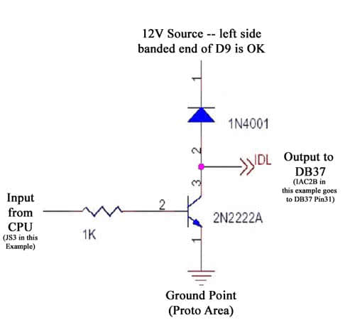
If you need TVIS activation, you basically stick with Jame’s document for the mini-circuit to activate…. but with these changes:
Instead of the:……………..Use:
X5 Output……………………JS3 Output
X14 (to pin 31)……………..IAC2B (to pin 31 on the DB37)
Ground DB37 7-11…………Ground at proto area ground point
12v D9 banded……………..Same is fine, 12v D9 Banded side
TunerStudio Config Changes: (if you use my map from the link above, which defaults to using FIDLE spark output as used with the PCB2.2 install)
On the Code Config > Codebase and Outputs Menu:
- Change FIDLE Function to Idle Control
- Change LED17 Function to Spark Output
OPTION C: The ‘Latest Greatest’. The MS-II PCB3.0
As with the other implementations, start by reading Jamesl’s document linked here: Jamesl’s Article
This actually isn’t all that different from the MS-I PCB3.0 with MSnS-E installation, the ignition input comes in on pin24 and needs a 12v pullup. The ignition output goes out on pin 36, here’s a difference though, you DO NOT need a 5v pullup on the ignition output with the MS-II as it has this pullup built-in. One other difference… you don’t need to do any mods for TVIS control as you won’t be using the FIDLE output for anything else so you can configure it as a ‘spare output’ and use it to control a relay controlling the TVIS system.
Mods Required
For the ignition input:
Use the Hall / Optical ignition input (step 50a) and jumper TachSelect to OptoIn, TSEL to OptoOut, and XG1 to XG2. We also need a 12v pullup. Install a 1k resistor between the right side (non-band) end of D1 and the left leg (banded end) of D9.
TVIS Activation
No mod required unless you are using FIDLE to control an idle valve, which on most MKI MR2’s isn’t needed due to the mechanical fast idle valve. So assuming you’re not using an FIDLE valve, just use pin30 (switched ground) to control a relay that triggers the TVIS solenoid.
Wiring
You can follow Jamesl’s original MS-I PCB2.2 document for building out MOST of your harness adapter. The exceptions are pin30 is now your TVIS control, and pin36 is now your ignition output. Otherwise you’re good to go.
This is laid out about as step by step as any MS installation out there as this one is very well researched and documented, and I’ve got a lot of hands on experience with it and experience helping others accomplish it as over the web as well. The nice thing about using this documentation is when finished you have a nice little plug-n-play adapter to use that makes a neat little connection into your stock wiring harness without hacking anything up.
As for what you need– here’s a page with info on my recommendations for a complete system: Which MegaSquirt Engine Management System is right for you?

